All ABOUT DIODE

Diode is a two-terminal electronic component with asymmetric conductance , it has low (ideally zero) resistance to current flow in one direction, and high (ideally infinite) resistance in the other. Today most diodes are made of silicon, but other semiconductors such as selenium or germanium are sometimes used. A semiconductor diode, the most common type today, is a crystalline piece of semiconductor material with a p–n junction connected to two electrical terminals.

image


FUNCTIONS

The most common function of a diode is to allow an electric current to pass in one direction (called the diode’s forward direction), while blocking current
in the opposite direction (the reverse direction). This unidirectional behavior is called rectification, and is used to convert alternating current to direct current, including extraction of modulation from radio signals in radio receivers—these diodes are forms of rectifiers .

Symbol of diode

image

CONNECTING DIODE PROPERLY

I hope you understand the positive and negative terminal of diode.
image

DIFFERENT TYPES OF DIODES

There are different types of  diodes and each of them have different function.

Zener diodes are used to regulate voltage.

avalanche diodes are used to protect circuits from high voltage surges.

varactor diodes are used to electronically tune radio and TV receivers.

tunnel diodes , Gunn diodes, IMPATT diodes are used  to generate radio frequency
oscillations.

light emitting diodes(LED) are used to produce light.

We will be using LEDs and photodiode or LDR in our projects, so here is the note on two. To know more about LED check out my Light Emitting Diode (LED) post or Connecting LED Properly post, to know more about LDR click here

Light-emitting diodes (LEDs)

In a diode formed from a direct band-gap semiconductor, such as gallium arsenide, carriers that cross the junction emit photons when they recombine with the majority carrier on the other side. Depending on the material, wavelengths (or colors) from the infrared to the near ultraviolet may be produced. The forward potential of these diodes depends on the wavelength of the emitted photons: 2.1 V corresponds to red, 4.0 V to violet. The first LEDs were red and yellow, and higher- frequency diodes have been developed over time. All LEDs produce incoherent, narrow- spectrum light; “white” LEDs are actually combinations of three LEDs of a different color, or a blue LED with a yellow scintillator coating. LEDs can also be used as low-efficiency photodiodes in signal applications. An LED may be paired with a photodiode or phototransistor in the same package, to form an opto- isolator .

Photodiodes

All semiconductors are subject to optical charge carrier generation. This is typically an undesired effect, so most semiconductors are packaged in light blocking material.
Photodiodes are intended to sense light( photodetector ), so they are packaged in materials that allow light to pass, and are usually PIN (the kind of diode most sensitive to light). A photodiode can be used in solar cells , in photometry, or in optical communications . Multiple photodiodes may be packaged in a single device

Most popular 1N-series diodes

We will be using 1N-series diodes. The standardized 1N-series numbering EIA370 system was introduced in the US by EIA/JEDEC (Joint Electron Device Engineering Council) about 1960. Among the most popular in this series were:
1N34A/1N270 (Germanium signal),
1N914/1N4148 (Silicon signal),
1N4001 -1N4007 (Silicon 1A power rectifier) and
1N54xx (Silicon 3A power rectifier)

If you want to know more about diode let me know it through the comments.

SPEAKER

A loudspeaker (or “speaker”) is an electroacoustic transducer that produces sound in response to an electrical audio signal input. Non-electrical loudspeakers were developed as accessories to telephone systems, but electronic amplification by.vacuum tube made loudspeakers more generally useful. The most common form of loudspeaker uses a paper cone which is vibrated by an attached voice coil electromagnet between the poles.of a permanent magnet, but many other types exist. Where high fidelity reproduction of sound is required, multiple loudspeakers may be used, each reproducing a part of the audible frequency range. Miniature loudspeakers are found in devices such as radio and TV receivers, and many forms of music players. Larger loudspeaker systems are used for music, sound reinforcement in theatres and concerts, and in public address systems.

Here is the picture of a 8R speaker we which we will be using in our project.

image

Symbol of speaker
image

The most common type of driver, commonly called a dynamic loudspeaker, uses a lightweight diaphragm , or cone , connected to a rigid basket, or frame, via a flexible suspension, commonly called a spider, that constrains a voice coil to move axially through a cylindrical magnetic gap. When an electrical signal is applied to the voice coil , a magnetic field is created by the electric current in the voice coil, making it a variable electromagnet. The coil and the driver’s magnetic system interact, generating a mechanical force that causes the coil (and thus, the attached cone) to move back and forth, thereby reproducing sound under the control of the applied electrical signal coming from the amplifier .

Modern driver magnets are almost always permanent and made of ceramic, ferrite, Alnico, or, more recently, rare earth such as neodymium and Samarium cobalt. The size and type of magnet and details of the magnetic circuit differ, depending on design goals.

MUSICAL BELL

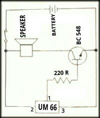
Today we are going to make a simple circuit that uses very few components and it produce sweet melody sound. This circuit uses a 3 terminal IC UM66. Usually this IC is used in greeting cards to make melody sound. The UM66 IC looks like a transistor with 3 terminals but it is a complete miniature tone generator with a tune and they come in variety of different tunes.

We have used a BC 548 NPN transistor for amplification and a 220R resistor to limit the base current. You can even include a switch in the circuit to keep the IC play the full music. Make sure that you do not give more than 4.5 V to UM 66.

image

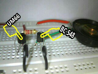
I have marked the IC UM66 and BC 548 transistor on the image below to clear your doubts.

image

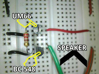
Here is an another angle of breadboard arrangement.

image

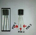
Here I have marked the pins of UM66. I hope this is useful.

image

COMPONENTS REQUIRED :-

1. UM66 IC
2. BC 548 transistor
3. 220R resistor
4. Speaker or buzzer
5. Battery 3V
6. Switch

CONNECTIONS :-

(MOST IMPORTANT :- Identify emitter, base, collector of transistor and pin number of IC UM66)

1. Connect a 220R resistor between pin1 of IC UM66 and base of transistor(connect middle pin of both transistors and IC).
2. Connect pin3 of IC UM66 and emitter pin of transistor to the base negative rail.
3. Connect pin2 of IC UM66 to the positive rail.
4. Take the speaker or buzzer and connect it between the collector pin and positive rail.
5. Now connect the battery and hear the melody sound.

If the musical bell is not working check the emitter, base, collector pins of transistor and pins of IC UM66 are connected properly. Still not working leave a comment and I will help you.

HOW TO CONNECT ELECTRONIC COMPONENTS

Here is a quick post on how to connect the basic electronic components correctly. These are cuts from my earlier post. This post is due to a suggestion  from my friend. He thought that a post like this can be used for quick reference and will be helpful to the starters. If you want to knew more about each components check out my other posts.

CONNECTING LED

A LED is a two-terminal electrical component, to identify them

Positive terminal can be identified as the longer leg and shorter leg is the negative terminal.
                         OR
If you look inside the LED you can see two small lead, fat one looks like a flag which is the cathode (negative) and other one looks almost straight which is the anode (positive). The symbol of LED is:-

image

CONNECTING RESISTOR

A resistor is a two-terminal electrical component

Resistor can be connected either way, that means it have no positive and negative terminal. Both symbols below are used to represent resistor in a circuit diagram. You can use any one of the two symbols:-

image

CONNECTING CAPACITOR

A capacitor is a two-terminal electrical component.

The ceramic capacitors can be connected either way, that means it have no positive and negative terminal. The symbol used for the ceramic capacitors in a circuit diagram is:-

image

The electrolytic capacitors have a positive terminal (longer leg) and negative terminal (shorter leg). The symbol used for the electrolytic capacitors in a circuit diagram is:-

image

CONNECTING LDR

LDR is also a two-terminal electrical which can be connected either way, that means it have no positive and negative terminal. The symbol of LDR is :-

image

CONNECTING NPN BJT
                                                  
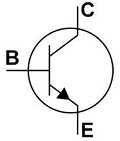
I have marked the  collector (C), base (B) and emitter (E) pins on a real NPN BJT and also on the symbol

image

CONNECTING PNP BJT

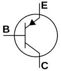
I have marked the  emitter (E), base (B) and collector (C) pins on a real PNP BJT and also on the symbol

image

CONNECTING 555 TIMER IC

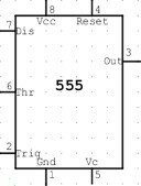
For connecting 555 timer check out this post The 555 timer IC pinout. I have marked each pin on a 555 timer IC and here is the symbol of 555 timer IC:-

image

Electronic Symbols | Schematic symbols

This post is for the starters out there who is having trouble in understanding the symbol of the circuit. I should have added this post before getting in to projects, here it is because of the request from my friend. I will add new symbol as we use them in our circuits. If you want more symbol OR have doubts on symbols, just leave a comment and I will help you.

RESISTOR

image

CAPACITOR
        1.electrolytic capacitor

image

        2. Ceramic capacitor

image

LED

image

BATTERY

image

LDR

image

555 TIMER IC

image

PNP TRANSISTOR

image

NPN TRANSISTOR

image

SPEAKER

image

SWITCH
     

image

PUSH SWITCH

image

GROUND CONNECTION

image

DIODE

image

BISTABLE MODE OF 555 IC

Bistable mode or Schmitt trigger :

A Bistable Mode or what is sometimes called a Schmitt Trigger, has two stable states, high and low. So in bistable mode 555 can operate as a flip-flop. Taking the Trigger input low makes the output of the circuit go into the high state. Taking the Reset input low makes the output of the circuit go into the low state. Remember that the discharge pin (pin 7) is not connected and no capacitor is used. Uses include bounce-free latched switches.

WORKING OF BISTABLE 555

In bistable mode, the 555 timer acts as a basic flip-flop. The  trigger and reset inputs (pins 2 and 4 respectively on a 555) are held high via Pull-up resistors while the threshold input (pin 6) is simply grounded. Thus configured, pulling the trigger momentarily to ground acts as a ‘set’ and transitions the output pin (pin 3) to Vcc (high state). Pulling the reset input to ground acts as a ‘reset’ and transitions the output pin to ground (low state). No capacitors are required in a bistable configuration. Pin 5 (control) is connected to ground via a small-value capacitor (10nF) pin 7 (discharge) is left floating.

MONOSTABLE MODE OF 555 IC

MONOSTABLE MODE :-

As I promised here is the post on monostable mode of 555 timer IC. In this mode, the 555 timer functions as a “one-shot” pulse generator. The name “monostable” meaning “one stable state”.

APPLICATION :-

Applications include timers, missing pulse detection, bouncefree switches, touch
switches, frequency divider, capacitance measurement, pulse-width modulation
(PWM) and so on. For example monostable 555 circuit is ideal for projects at exhibitions, which needed to work when a visitor pushes the button to start the project’s mechanism moving, and the mechanism will automatically switch off after the time you set.

WORKING OF MONOSTABLE 555 TIMER

In this mode 555 acts as a pulse generator and the pulse starts  when the 555 timer receives a input at the trigger input (pin 2) that falls below a third of the voltage supply.The width of the output pulse is determined by the time constant of an RC network, which consists of a capacitor (C) and a resistor (R). The output pulse ends when the voltage on the capacitor (C)  equals 2/3 of the supply voltage( Vcc). The output pulse width can be lengthened or shortened to your need just by adjusting the values of the capacitor (C) and a resistor (R).

CONNECTION :-

Reset (pin 4) and pin 8 is connected to positive voltage (Vcc).

Discharge pin (pin 7) and threshold (pin 6) pins share a common node (means connected).

Resistor R is connected between the Vcc and the common node that is shared by the discharge pin (pin 7) and threshold (pin 6).

Capacitor C is connected between the common node that is shared by the discharge pin (pin 7) and threshold (pin 6) and GND.

Pin 1 is connected to GND.

A 10n capacitor is connected between control (pin 5) and GND.

Here is all about monostable mode of 555 timer IC. My next post will be on bistable mode of 555 timer IC. If you have any doubts or you like the post, put it in the comment box below.

ASTABLE MODE OF 555 IC

ASTABLE MODE

Here is the post about the different working mode of 555 timer IC as I promised on the 555 timer post. An Astable mode 555 timer IC has no stable state – hence the name “astable”. That means output continually switches state between high and low without any intervention from the user, called a ‘square’ wave. This type of circuit could be used for switching a motor on and off at regular intervals. It can also be used to flash lamps and LEDs, and is useful as a ‘clock’ pulse for other digital ICs and circuits.

CONNECTION :-

Reset (pin 4) and pin 8 is connected to positive voltage (Vcc).

Resistor R 1 is connected between Vcc and the discharge pin (pin 7).

Trigger (pin 2) and threshold (pin 6) pins share a common node (means connected).

Another resistor (R 2) is connected between the discharge pin (pin 7), and the common node that is shared by the trigger (pin 2) and threshold (pin 6).

Capacitor (C 1) is connected between the common node that is shared by the trigger (pin 2) and threshold (pin 6) and GND.

Pin 1 is connected to GND.

A 10n capacitor is connected between control (pin 5) and GND.

OUTPUT

In astable mode, the 555 timer puts out a continuous stream of rectangular pulses having a specified frequency at output (pin 3).

My next post will be on monostable mode of 555 timer IC. If you find this post useful, let me know it through the comments.
LED DIMMER

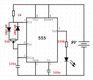
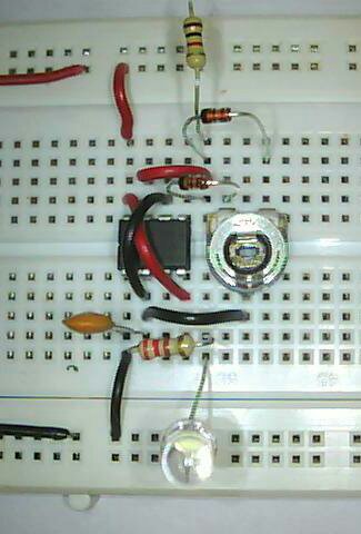
This is a simple circuit that will adjust the brightness of one or more LEDs from 5% to 95%. I have used only only one LED. Only place where you can go wrong in this project is while connecting the diode, so connect the diode properly.

I will add the connections later.

image

image

In my breadboard arrangement I have not connected the 100n between the pin5 and negative rail and the resistor I used is 220R instead of 330R in the circuit diagram.

COMPONENTS REQUIRED:

1. 555 timer IC
2. 47k POT
3. 1N4148 diode x2
4. 1k resistor
5. 330R resistor
6. 100nf capacitor (code 104) x2
7. LED
8. Battery

FADING LED

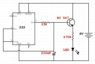
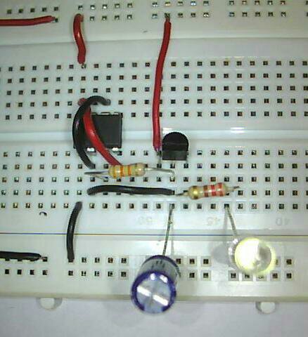
If you want a fading effect on the FLASHING LED project check this out. This circuit will make the LED fade up and down in the same manner.By adjusting the value of resistor you will get a better fading effect. The resistor connected to the LED is important in this circuit.

IF CIRCUIT IS NOT WORKING

1. Firstly check the transistor connection
2. Usually the mistake is made while connecting the 220mf capacitor, circuit is little confusing there, so look at my breadboard connection and the circuit diagram properly.

I will add the connections later.

image

image

COMPONENTS REQUIRED :

1. 555 timer IC
2. 220mf capacitor
3. 33k resistor
4. 470R resistor
5. BC547 transistor
6. LED
7. Battery