HOW TO CONNECT ELECTRONIC COMPONENTS

Here is a quick post on how to connect the basic electronic components correctly. These are cuts from my earlier post. This post is due to a suggestion  from my friend. He thought that a post like this can be used for quick reference and will be helpful to the starters. If you want to knew more about each components check out my other posts.

CONNECTING LED

A LED is a two-terminal electrical component, to identify them

Positive terminal can be identified as the longer leg and shorter leg is the negative terminal.
                         OR
If you look inside the LED you can see two small lead, fat one looks like a flag which is the cathode (negative) and other one looks almost straight which is the anode (positive). The symbol of LED is:-

image

CONNECTING RESISTOR

A resistor is a two-terminal electrical component

Resistor can be connected either way, that means it have no positive and negative terminal. Both symbols below are used to represent resistor in a circuit diagram. You can use any one of the two symbols:-

image

CONNECTING CAPACITOR

A capacitor is a two-terminal electrical component.

The ceramic capacitors can be connected either way, that means it have no positive and negative terminal. The symbol used for the ceramic capacitors in a circuit diagram is:-

image

The electrolytic capacitors have a positive terminal (longer leg) and negative terminal (shorter leg). The symbol used for the electrolytic capacitors in a circuit diagram is:-

image

CONNECTING LDR

LDR is also a two-terminal electrical which can be connected either way, that means it have no positive and negative terminal. The symbol of LDR is :-

image

CONNECTING NPN BJT
                                                  
I have marked the  collector (C), base (B) and emitter (E) pins on a real NPN BJT and also on the symbol

image

CONNECTING PNP BJT

I have marked the  emitter (E), base (B) and collector (C) pins on a real PNP BJT and also on the symbol

image

CONNECTING 555 TIMER IC

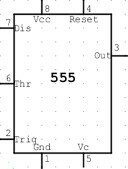
For connecting 555 timer check out this post The 555 timer IC pinout. I have marked each pin on a 555 timer IC and here is the symbol of 555 timer IC:-

image

CONNECTING LED PROPERLY

It’s important to connect a LED the correct way in a circuit because LED shows the output in many of the circuit that we are going to discuss. LED is simple to connect – once you know how.
I thought that it is important for starters to connect a LED in the proper way. This post is only to show how a LED can be connected to batteries without damaging it.

Let’s look into three example of connecting LED. I took these three example because all three situation can happen when you start your electronic journey.LED not glowing. LED gets damaged connecting to some batteries. Don’t know which resistor should be connected to which LED and to what battery. This all happened to me when I was 7-8 years old. I hope you don’t have any problem connecting LED after reading this post. Let’s get started.

Before connecting LED you must remember that LED must have a resistor to limit the current. It does not matter if the resistor is connected above or below the LED. The circuits are the SAME. If you have problem in identifying the positive and negative terminal of LED check out my Light Emitting Diode (LED) post

The LED in the first diagram (A) does not illuminate because a red LED requires 1.7v and the cell only supplies 1.5v.

The red LED in the second diagram (B) is damaged because it requires 1.7v and the two cells supply 3v.

To connect a red LED properly, resistor is needed to limit the current to about 25mA and also the voltage to 1.7v, as shown in the third diagram (C) as a result LED glow.

image

Here is little something for clearing you doubts about what if I change the value of the resistor, LED and battery. Here I have given some common LED and how to connect it to different voltages.

Red super bright (1.85V 20mA)
9V – 360R
7.5V – 280R
6V – 210R
4.5V – 130R
3V – 60R

Red bright (2.0V 10mA)
9V – 700R
7.5V – 550R
6V – 400R
4.5V – 250R
3V – 100R

Green standard (2.2V 10mA)
9V – 680R
7.5V – 530R
6V – 380R
4.5V – 230R
3V – 80R

Super blue (3.6V 20mA)
White cool (3.6V 20mA)
9V – 270R
7.5V – 190R
6V – 120R
4.5V – 40R

Orange standard (2.1V 10mA)
Yellow standard (2.1V 10mA)
9V – 690R
7.5V – 540R
6V – 390R
4.5V – 240R
3V – 90R

Blue high intensity (4.5V 20mA)
9V – 220R
7.5V – 150R
6V – 70R

Remember this voltage we apply (Vcc) must be greater than voltage drop of LED, this is the reason why some LED won’t work on 3V.

If you want to know more about LED check out my Light Emitting Diode (LED) post.
Feel free to comment.