Here is a quick post on how to connect the basic electronic components correctly. These are cuts from my earlier post. This post is due to a suggestion from my friend. He thought that a post like this can be used for quick reference and will be helpful to the starters. If you want to knew more about each components check out my other posts.
CONNECTING LED
A LED is a two-terminal electrical component, to identify them
Positive terminal can be identified as the longer leg and shorter leg is the negative terminal.
OR
If you look inside the LED you can see two small lead, fat one looks like a flag which is the cathode (negative) and other one looks almost straight which is the anode (positive). The symbol of LED is:-
CONNECTING RESISTOR
A resistor is a two-terminal electrical component
Resistor can be connected either way, that means it have no positive and negative terminal. Both symbols below are used to represent resistor in a circuit diagram. You can use any one of the two symbols:-
CONNECTING CAPACITOR
A capacitor is a two-terminal electrical component.
The ceramic capacitors can be connected either way, that means it have no positive and negative terminal. The symbol used for the ceramic capacitors in a circuit diagram is:-
The electrolytic capacitors have a positive terminal (longer leg) and negative terminal (shorter leg). The symbol used for the electrolytic capacitors in a circuit diagram is:-
CONNECTING LDR
LDR is also a two-terminal electrical which can be connected either way, that means it have no positive and negative terminal. The symbol of LDR is :-
CONNECTING NPN BJT
I have marked the collector (C), base (B) and emitter (E) pins on a real NPN BJT and also on the symbol
CONNECTING PNP BJT
I have marked the emitter (E), base (B) and collector (C) pins on a real PNP BJT and also on the symbol
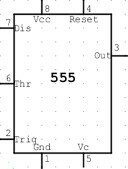
CONNECTING 555 TIMER IC
For connecting 555 timer check out this post The 555 timer IC pinout. I have marked each pin on a 555 timer IC and here is the symbol of 555 timer IC:-


