MUSICAL BELL

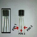
Today we are going to make a simple circuit that uses very few components and it produce sweet melody sound. This circuit uses a 3 terminal IC UM66. Usually this IC is used in greeting cards to make melody sound. The UM66 IC looks like a transistor with 3 terminals but it is a complete miniature tone generator with a tune and they come in variety of different tunes.

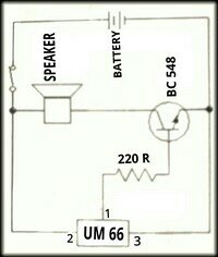
We have used a BC 548 NPN transistor for amplification and a 220R resistor to limit the base current. You can even include a switch in the circuit to keep the IC play the full music. Make sure that you do not give more than 4.5 V to UM 66.

image

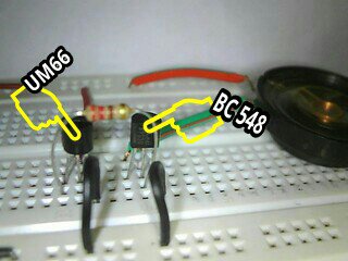
I have marked the IC UM66 and BC 548 transistor on the image below to clear your doubts.

image

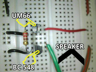
Here is an another angle of breadboard arrangement.

image

Here I have marked the pins of UM66. I hope this is useful.

image

COMPONENTS REQUIRED :-

1. UM66 IC
2. BC 548 transistor
3. 220R resistor
4. Speaker or buzzer
5. Battery 3V
6. Switch

CONNECTIONS :-

(MOST IMPORTANT :- Identify emitter, base, collector of transistor and pin number of IC UM66)

1. Connect a 220R resistor between pin1 of IC UM66 and base of transistor(connect middle pin of both transistors and IC).
2. Connect pin3 of IC UM66 and emitter pin of transistor to the base negative rail.
3. Connect pin2 of IC UM66 to the positive rail.
4. Take the speaker or buzzer and connect it between the collector pin and positive rail.
5. Now connect the battery and hear the melody sound.

If the musical bell is not working check the emitter, base, collector pins of transistor and pins of IC UM66 are connected properly. Still not working leave a comment and I will help you.
BISTABLE MODE OF 555 IC

Bistable mode or Schmitt trigger :

A Bistable Mode or what is sometimes called a Schmitt Trigger, has two stable states, high and low. So in bistable mode 555 can operate as a flip-flop. Taking the Trigger input low makes the output of the circuit go into the high state. Taking the Reset input low makes the output of the circuit go into the low state. Remember that the discharge pin (pin 7) is not connected and no capacitor is used. Uses include bounce-free latched switches.

WORKING OF BISTABLE 555

In bistable mode, the 555 timer acts as a basic flip-flop. The  trigger and reset inputs (pins 2 and 4 respectively on a 555) are held high via Pull-up resistors while the threshold input (pin 6) is simply grounded. Thus configured, pulling the trigger momentarily to ground acts as a ‘set’ and transitions the output pin (pin 3) to Vcc (high state). Pulling the reset input to ground acts as a ‘reset’ and transitions the output pin to ground (low state). No capacitors are required in a bistable configuration. Pin 5 (control) is connected to ground via a small-value capacitor (10nF) pin 7 (discharge) is left floating.

MONOSTABLE MODE OF 555 IC

MONOSTABLE MODE :-

As I promised here is the post on monostable mode of 555 timer IC. In this mode, the 555 timer functions as a “one-shot” pulse generator. The name “monostable” meaning “one stable state”.

APPLICATION :-

Applications include timers, missing pulse detection, bouncefree switches, touch
switches, frequency divider, capacitance measurement, pulse-width modulation
(PWM) and so on. For example monostable 555 circuit is ideal for projects at exhibitions, which needed to work when a visitor pushes the button to start the project’s mechanism moving, and the mechanism will automatically switch off after the time you set.

WORKING OF MONOSTABLE 555 TIMER

In this mode 555 acts as a pulse generator and the pulse starts  when the 555 timer receives a input at the trigger input (pin 2) that falls below a third of the voltage supply.The width of the output pulse is determined by the time constant of an RC network, which consists of a capacitor (C) and a resistor (R). The output pulse ends when the voltage on the capacitor (C)  equals 2/3 of the supply voltage( Vcc). The output pulse width can be lengthened or shortened to your need just by adjusting the values of the capacitor (C) and a resistor (R).

CONNECTION :-

Reset (pin 4) and pin 8 is connected to positive voltage (Vcc).

Discharge pin (pin 7) and threshold (pin 6) pins share a common node (means connected).

Resistor R is connected between the Vcc and the common node that is shared by the discharge pin (pin 7) and threshold (pin 6).

Capacitor C is connected between the common node that is shared by the discharge pin (pin 7) and threshold (pin 6) and GND.

Pin 1 is connected to GND.

A 10n capacitor is connected between control (pin 5) and GND.

Here is all about monostable mode of 555 timer IC. My next post will be on bistable mode of 555 timer IC. If you have any doubts or you like the post, put it in the comment box below.

ASTABLE MODE OF 555 IC

ASTABLE MODE

Here is the post about the different working mode of 555 timer IC as I promised on the 555 timer post. An Astable mode 555 timer IC has no stable state – hence the name “astable”. That means output continually switches state between high and low without any intervention from the user, called a ‘square’ wave. This type of circuit could be used for switching a motor on and off at regular intervals. It can also be used to flash lamps and LEDs, and is useful as a ‘clock’ pulse for other digital ICs and circuits.

CONNECTION :-

Reset (pin 4) and pin 8 is connected to positive voltage (Vcc).

Resistor R 1 is connected between Vcc and the discharge pin (pin 7).

Trigger (pin 2) and threshold (pin 6) pins share a common node (means connected).

Another resistor (R 2) is connected between the discharge pin (pin 7), and the common node that is shared by the trigger (pin 2) and threshold (pin 6).

Capacitor (C 1) is connected between the common node that is shared by the trigger (pin 2) and threshold (pin 6) and GND.

Pin 1 is connected to GND.

A 10n capacitor is connected between control (pin 5) and GND.

OUTPUT

In astable mode, the 555 timer puts out a continuous stream of rectangular pulses having a specified frequency at output (pin 3).

My next post will be on monostable mode of 555 timer IC. If you find this post useful, let me know it through the comments.

LED DIMMER

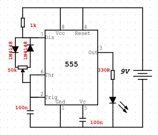
This is a simple circuit that will adjust the brightness of one or more LEDs from 5% to 95%. I have used only only one LED. Only place where you can go wrong in this project is while connecting the diode, so connect the diode properly.

I will add the connections later.

image

image

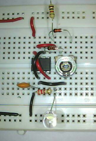
In my breadboard arrangement I have not connected the 100n between the pin5 and negative rail and the resistor I used is 220R instead of 330R in the circuit diagram.

COMPONENTS REQUIRED:

1. 555 timer IC
2. 47k POT
3. 1N4148 diode x2
4. 1k resistor
5. 330R resistor
6. 100nf capacitor (code 104) x2
7. LED
8. Battery

FLASHING LED

This is a simple LED project for starters and one of the first LED project that I did .It will make the LED flashing at the rate I decide . I had lot of fun doing this one , every time I changed the value of resistor or capacitor , LED keep changing the time between flashing . Let’s build this thing.

image

image

Connection :-

1 . Connect pin 2 and pin 6 of 555 IC
2 . Connect pin 4 and Pin 8 of 555 IC
3 . Connect 47mF capacitor +ve ( longer leg ) to pin 2 and -ve to ground.
4 . Connect +ve (longer leg leg ) of LED to pin 3 and -ve to pin 1
5 . Now connect one of the 10k resistor between pin 8 and pin 7
6 . Now connect other 10k resistor between pin 7and pin 6
7. Finish the circuit with battery connection , +ve to pin 8 and -ve to pin 1

If you have problem in identifying the pins of 555 timer IC checkout my post on the 555 timer IC which helps to identify the pins and the function of each pins.

If your connection are correct LED Will be flashing . If you are haveing problem with circuit , leave a comment and I Will help you.

Components Required :-

1. Resistor – 10k x 2
2. Capacitor – 47mF
3. White LED
4. 555 IC
6. Wire
7. 9V battery

SIMPLE TRANSISTOR CIRCUIT

This is the simplest circuit you can make with a transistors. You can use any NPN transistors. Here I have used BC 547. In this  project the transistor is turned on via a finger.

Connect the LED, 220 ohm resistor and transistor as shown in the circuit. Touch the top point with two fingers of one hand and the lower point with fingers of the other hand and squeeze. As you press harder, the resistance of your finger decreases. This allows more current to flow into the base and the transistor turns on more and more. Your body has resistance and when a voltage is present, current will flow though your body (fingers). The transistor is amplifying the current through your fingers and this is enough to illuminate the LED.

image

image

If you have trouble in identifying the base, emitter, and collector check out my post on the BJT.

CONNECTION

1. Connect emitter (E) of the transistor to negative terminal of battery.
2. Resistor:- Connect the resistor between the collector (C) and negative of the LED
3. Now connect the positive terminal of both LED and battery.
4. Now connect the touch wire and if you touch those wire LED glow.

COMPONENTS REQUIRED :

1. BC 547 Transistor
2. 220R Resistor
3. LED
4. Battery

To make sure this is working simply press on the two wires and the LED will illuminate brighter and if not leave a comment and I will help you.
CONNECTING LED PROPERLY

It’s important to connect a LED the correct way in a circuit because LED shows the output in many of the circuit that we are going to discuss. LED is simple to connect – once you know how.
I thought that it is important for starters to connect a LED in the proper way. This post is only to show how a LED can be connected to batteries without damaging it.

Let’s look into three example of connecting LED. I took these three example because all three situation can happen when you start your electronic journey.LED not glowing. LED gets damaged connecting to some batteries. Don’t know which resistor should be connected to which LED and to what battery. This all happened to me when I was 7-8 years old. I hope you don’t have any problem connecting LED after reading this post. Let’s get started.

Before connecting LED you must remember that LED must have a resistor to limit the current. It does not matter if the resistor is connected above or below the LED. The circuits are the SAME. If you have problem in identifying the positive and negative terminal of LED check out my Light Emitting Diode (LED) post

The LED in the first diagram (A) does not illuminate because a red LED requires 1.7v and the cell only supplies 1.5v.

The red LED in the second diagram (B) is damaged because it requires 1.7v and the two cells supply 3v.

To connect a red LED properly, resistor is needed to limit the current to about 25mA and also the voltage to 1.7v, as shown in the third diagram (C) as a result LED glow.

image

Here is little something for clearing you doubts about what if I change the value of the resistor, LED and battery. Here I have given some common LED and how to connect it to different voltages.

Red super bright (1.85V 20mA)
9V – 360R
7.5V – 280R
6V – 210R
4.5V – 130R
3V – 60R

Red bright (2.0V 10mA)
9V – 700R
7.5V – 550R
6V – 400R
4.5V – 250R
3V – 100R

Green standard (2.2V 10mA)
9V – 680R
7.5V – 530R
6V – 380R
4.5V – 230R
3V – 80R

Super blue (3.6V 20mA)
White cool (3.6V 20mA)
9V – 270R
7.5V – 190R
6V – 120R
4.5V – 40R

Orange standard (2.1V 10mA)
Yellow standard (2.1V 10mA)
9V – 690R
7.5V – 540R
6V – 390R
4.5V – 240R
3V – 90R

Blue high intensity (4.5V 20mA)
9V – 220R
7.5V – 150R
6V – 70R

Remember this voltage we apply (Vcc) must be greater than voltage drop of LED, this is the reason why some LED won’t work on 3V.

If you want to know more about LED check out my Light Emitting Diode (LED) post.
Feel free to comment.

Starter Electronic First Page

Hi everyone ,

This is my first blog.Here I share some of the simple circuit diagram. I hope this will be useful to the starters out there.I will be starting my blog with small post on the basic electronic components such as resistor, capacitor, LED, IC’s, etc…. Where you can find how to connect it, symbol of the component, how the real one look like, and some other information.

Here I will be starting with simple circuits , that we see around us such as flashing LED at regular intervals, fading the LED up and down, adjusting the brightness of the LED, LED chaser or dancing LED, OR even we can make a small clap switch, OR a small LED cube, OR a small line following robot without any programming. All the above can be easily made using few components which will be easily available in almost all electronics shops. We Will be using 555 IC , transistor , resistor , capacitor , breadboard , connecting wire etc… to create wonderful projects. The next post have a list of items that you need the most to start your electronics journey. I hope you will enjoy making the projects .Every circuit is tested and 100% working. If there are any doubts or suggestions regarding any circuit , let me know and I will do my level best to clear it.

If you like the project let me know it through the comments .