BISTABLE MODE OF 555 IC

Bistable mode or Schmitt trigger :

A Bistable Mode or what is sometimes called a Schmitt Trigger, has two stable states, high and low. So in bistable mode 555 can operate as a flip-flop. Taking the Trigger input low makes the output of the circuit go into the high state. Taking the Reset input low makes the output of the circuit go into the low state. Remember that the discharge pin (pin 7) is not connected and no capacitor is used. Uses include bounce-free latched switches.

WORKING OF BISTABLE 555

In bistable mode, the 555 timer acts as a basic flip-flop. The  trigger and reset inputs (pins 2 and 4 respectively on a 555) are held high via Pull-up resistors while the threshold input (pin 6) is simply grounded. Thus configured, pulling the trigger momentarily to ground acts as a ‘set’ and transitions the output pin (pin 3) to Vcc (high state). Pulling the reset input to ground acts as a ‘reset’ and transitions the output pin to ground (low state). No capacitors are required in a bistable configuration. Pin 5 (control) is connected to ground via a small-value capacitor (10nF) pin 7 (discharge) is left floating.

MONOSTABLE MODE OF 555 IC

MONOSTABLE MODE :-

As I promised here is the post on monostable mode of 555 timer IC. In this mode, the 555 timer functions as a “one-shot” pulse generator. The name “monostable” meaning “one stable state”.

APPLICATION :-

Applications include timers, missing pulse detection, bouncefree switches, touch
switches, frequency divider, capacitance measurement, pulse-width modulation
(PWM) and so on. For example monostable 555 circuit is ideal for projects at exhibitions, which needed to work when a visitor pushes the button to start the project’s mechanism moving, and the mechanism will automatically switch off after the time you set.

WORKING OF MONOSTABLE 555 TIMER

In this mode 555 acts as a pulse generator and the pulse starts  when the 555 timer receives a input at the trigger input (pin 2) that falls below a third of the voltage supply.The width of the output pulse is determined by the time constant of an RC network, which consists of a capacitor (C) and a resistor (R). The output pulse ends when the voltage on the capacitor (C)  equals 2/3 of the supply voltage( Vcc). The output pulse width can be lengthened or shortened to your need just by adjusting the values of the capacitor (C) and a resistor (R).

CONNECTION :-

Reset (pin 4) and pin 8 is connected to positive voltage (Vcc).

Discharge pin (pin 7) and threshold (pin 6) pins share a common node (means connected).

Resistor R is connected between the Vcc and the common node that is shared by the discharge pin (pin 7) and threshold (pin 6).

Capacitor C is connected between the common node that is shared by the discharge pin (pin 7) and threshold (pin 6) and GND.

Pin 1 is connected to GND.

A 10n capacitor is connected between control (pin 5) and GND.

Here is all about monostable mode of 555 timer IC. My next post will be on bistable mode of 555 timer IC. If you have any doubts or you like the post, put it in the comment box below.

ASTABLE MODE OF 555 IC

ASTABLE MODE

Here is the post about the different working mode of 555 timer IC as I promised on the 555 timer post. An Astable mode 555 timer IC has no stable state – hence the name “astable”. That means output continually switches state between high and low without any intervention from the user, called a ‘square’ wave. This type of circuit could be used for switching a motor on and off at regular intervals. It can also be used to flash lamps and LEDs, and is useful as a ‘clock’ pulse for other digital ICs and circuits.

CONNECTION :-

Reset (pin 4) and pin 8 is connected to positive voltage (Vcc).

Resistor R 1 is connected between Vcc and the discharge pin (pin 7).

Trigger (pin 2) and threshold (pin 6) pins share a common node (means connected).

Another resistor (R 2) is connected between the discharge pin (pin 7), and the common node that is shared by the trigger (pin 2) and threshold (pin 6).

Capacitor (C 1) is connected between the common node that is shared by the trigger (pin 2) and threshold (pin 6) and GND.

Pin 1 is connected to GND.

A 10n capacitor is connected between control (pin 5) and GND.

OUTPUT

In astable mode, the 555 timer puts out a continuous stream of rectangular pulses having a specified frequency at output (pin 3).

My next post will be on monostable mode of 555 timer IC. If you find this post useful, let me know it through the comments.

LED DIMMER

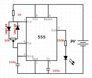
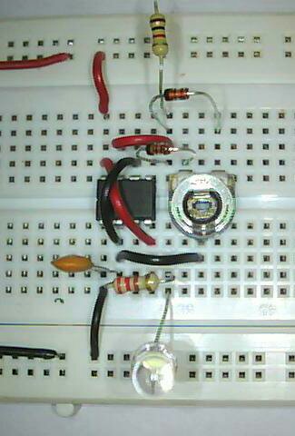
This is a simple circuit that will adjust the brightness of one or more LEDs from 5% to 95%. I have used only only one LED. Only place where you can go wrong in this project is while connecting the diode, so connect the diode properly.

I will add the connections later.

image

image

In my breadboard arrangement I have not connected the 100n between the pin5 and negative rail and the resistor I used is 220R instead of 330R in the circuit diagram.

COMPONENTS REQUIRED:

1. 555 timer IC
2. 47k POT
3. 1N4148 diode x2
4. 1k resistor
5. 330R resistor
6. 100nf capacitor (code 104) x2
7. LED
8. Battery

FADING LED

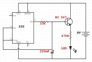
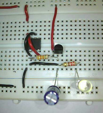
If you want a fading effect on the FLASHING LED project check this out. This circuit will make the LED fade up and down in the same manner.By adjusting the value of resistor you will get a better fading effect. The resistor connected to the LED is important in this circuit.

IF CIRCUIT IS NOT WORKING

1. Firstly check the transistor connection
2. Usually the mistake is made while connecting the 220mf capacitor, circuit is little confusing there, so look at my breadboard connection and the circuit diagram properly.

I will add the connections later.

image

image

COMPONENTS REQUIRED :

1. 555 timer IC
2. 220mf capacitor
3. 33k resistor
4. 470R resistor
5. BC547 transistor
6. LED
7. Battery

FLASHING LED

This is a simple LED project for starters and one of the first LED project that I did .It will make the LED flashing at the rate I decide . I had lot of fun doing this one , every time I changed the value of resistor or capacitor , LED keep changing the time between flashing . Let’s build this thing.

image

image

Connection :-

1 . Connect pin 2 and pin 6 of 555 IC
2 . Connect pin 4 and Pin 8 of 555 IC
3 . Connect 47mF capacitor +ve ( longer leg ) to pin 2 and -ve to ground.
4 . Connect +ve (longer leg leg ) of LED to pin 3 and -ve to pin 1
5 . Now connect one of the 10k resistor between pin 8 and pin 7
6 . Now connect other 10k resistor between pin 7and pin 6
7. Finish the circuit with battery connection , +ve to pin 8 and -ve to pin 1

If you have problem in identifying the pins of 555 timer IC checkout my post on the 555 timer IC which helps to identify the pins and the function of each pins.

If your connection are correct LED Will be flashing . If you are haveing problem with circuit , leave a comment and I Will help you.

Components Required :-

1. Resistor – 10k x 2
2. Capacitor – 47mF
3. White LED
4. 555 IC
6. Wire
7. 9V battery

SIMPLE SECURITY

This is the simple security system that you can build for your own.You have already seen in movies , somebody cross the red laser line the alarm starts. You can build something like that for your own room.

Here I have placed a buzzer but you can also place a LED or other small project.

SETUP FOR THIS PROJECT :-

For setup your security all you have to do is, put a laser (I recommend laser) or a light source such as LED on one end of the door and place the LDR on other end in such a way that laser beam falls on LDR. This project work on the simple principle that, as someone enter your room the laser beam is cutoff. LDR detect this (absence of light) and trigger the buzzer.

image

CONNECTIONS :-

1. Place the LDR between base and emitter of transistor.
2. Connect a 10k resistor between base and +ve terminal of buzzer.
3. Connect -ve of buzzer to collector of transistor.
4. Now connect +ve of battery to +ve of buzzer and -ve of battery to emitter of transistor.

COMPONENTS  REQUIRED :-

1.BC547 transistor
2.10k resistor
3. LDR
4. Buzzer
5. Battery

THE 555 TIMER IC PINOUT

The 555  timer IC is an integrated circuit (chip) used in a variety of timer, pulse generation, and oscillator applications. The 555 can be used to provide time delays, as an oscillator, and as a flip-flop element. The primary purpose of the 555 timer is the generation of accurately timed single pulse or oscillatory pulse waveforms. The 555 has three main operating modes Monostable, Astable, and Bistable. Each mode represents a different type of circuit that has a particular output. I will make a post on the 555 main three operating modes later.

THE FUNCTION OF EACH PINS

Pin 1 Ground [GND] – Most negative supply connected to the device, normally this is common ground (0V).

Pin 2 Trigger [TRIG] – Detects 1/3 of rail voltage to make output HIGH.

Pin 3 Output [OUT] – The 555 timer output signal pin.

Pin 4 Reset [RES] – reset. Must be taken below 0.8v to reset the chip

Pin 5 Control [CON] – A voltage applied to this pin will vary the timing of the RC network

Pin 6 Threshold [THRESH] – Detects 2/3 of rail voltage to make output LOW only if pin 2 is HIGH

Pin 7 Discharge [DIS] – Goes LOW when pin 6 detects 2/3 rail voltage but pin 2 must be HIGH.

Pin 8 VCC [VCC] – Most positive supply connected to device, normally this is 5V, 10V or 15V.

555 IC PINOUT

To identify the Pin1, place the 555 on a flat surface such a way that the small circle is in the top left corner.Now identification of pins are easy. Now start from the top left corner (where the small circle is) first pin is pin1, next pin below is pin2, next pin below is pin3, next pin below is pin4, pin5 is on the bottom right corner, next pin above is pin6, next pin above is pin7, next pin above is pin8.

To identify the pins of IC start from the top left corner where the small circle is and the top first pin will be pin1 and start counting in the pins in anticlockwise direction pin 2, pin 3, pin 4….and stop at the first pin on the top right corner which in the case of 555 is pin 8.

Here I have marked the 8 pins on a 555 iC:-

image

For the easy understanding of the circuit we always draw the 555 as a building block, as shown below with the pins in the following locations. I have given functions of each pin next to it. So you can remember it easily. I hope you can understand it.

555

If you have doubt in identify the pins of 555 IC OR function of each pin, put it in the comments and I will help you to solve it.
Starter Electronic First Page

Hi everyone ,

This is my first blog.Here I share some of the simple circuit diagram. I hope this will be useful to the starters out there.I will be starting my blog with small post on the basic electronic components such as resistor, capacitor, LED, IC’s, etc…. Where you can find how to connect it, symbol of the component, how the real one look like, and some other information.

Here I will be starting with simple circuits , that we see around us such as flashing LED at regular intervals, fading the LED up and down, adjusting the brightness of the LED, LED chaser or dancing LED, OR even we can make a small clap switch, OR a small LED cube, OR a small line following robot without any programming. All the above can be easily made using few components which will be easily available in almost all electronics shops. We Will be using 555 IC , transistor , resistor , capacitor , breadboard , connecting wire etc… to create wonderful projects. The next post have a list of items that you need the most to start your electronics journey. I hope you will enjoy making the projects .Every circuit is tested and 100% working. If there are any doubts or suggestions regarding any circuit , let me know and I will do my level best to clear it.

If you like the project let me know it through the comments .